

In part 2 of the Gas Metal Arc Welding blog we will break down the gas shielding system and discuss the function, parts involved and how to troubleshoot gas shielding issues.
Gas Shielding
The gas shielding system is not that complex. Gas is delivered via regulator and flow control flow meter on the cylinder and then through an on / off solenoid which is turned on and off with the trigger so it coincides with wire feed and the gas is delivered down to the torch. A common mistake by welders is to turn the gas up excessively. Having the gas too high can create just as many problems as having it too low. Too low means that the weld will not be adequately shielded. Too high gas flow results in turbulence whereby the gas will hit the plate and vortex and drag some of the atmosphere into the shielding gas which can also cause porosity in the weld, this also means you are consuming too much gas.
 |
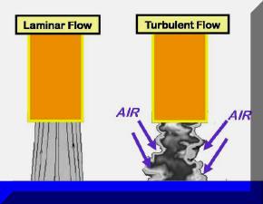 |
| Porosity caused by insufficient gas shielding | Turbulence causing atmospheric contamination |
Shielding Gas Mixes
Shielding gas mixes are extremely important as the gas mix has a dramatic effect on the arc characteristics. The effect of gases will be talked about in detail in a separate blog but as a starting point use the following;
- Straight argon when welding aluminium and magnesium.
- Argon, 16% CO2 and 2 to 3% oxygen when welding carbon steel.
- Argon, and 25% CO2 or alternatively straight CO2 should be used with flux core wire.
- When we are welding stainless steel use helium mixed gas which is typically argon, 35% helium, and very small additions of CO2, a helium mix is also used for heavy aluminium to offset the high sink of the thick aluminium.
 |
 |
| 16% CO2 / 3% O2 in Argon cylinder | 25% CO2 in Argon cylinder |
 |
 |
| CO2 Gas cylinder | 100% Argon cylinder |
Flow Rate and Connections
The flow rate is dependent on gas density, argon rich gases should be run at approximately 15 to 18Lpm because they are heavier than air, helium base gases need to have a slightly higher flow rate to account for the fact helium is lighter than air, helium mix gases should be run at approximately 18 to 20Lpm.
The key to ensuring you don’t have a problem with your gas system, in the introduction of atmospheric contamination and therefore a reduction of the purity of your shielding gas, is to ensure connections are tight, check the hoses are not damaged, and all of the O-rings are in good condition. There are a number of connections that you need to ensure are in good condition; let’s start at the cylinder, on the bottom of the regulator there is an O-ring that should be in good condition, never lubricated, and when the regulator is put into the cylinder the regulator nut should not be overtightened.
If you are running a separate flowmeter the connection between the regulator and the flow meter needs to be sound. The flowmeter should always stand vertical to ensure you have an accurate reading and it should be the correct type for the gas you are using. Different types of flow meters’ measure at different locations. Bobbin type at the top of the bobbin, ball type to the centre of the ball. If you’re unsure read the instructions that are directly on the flowmeter.
 |
 |
| Flow meter connected to regulator | Ball type flow meter |
 |
 |
| Argon hose connection | Hose connection to back of machine |
The next connection is the flow meter to the hose and the nut that connects the hose to the flowmeter. This should be firm but never over tightened, the male and female component should be of the same type because it relies on the brass seat to create an effective seal. The connection between the nut and male component, what is referred to as the tail where the hose is attached to that connection should be in good condition and there should be no cracks in the hose from damage.
The next connection is where the hose goes into the back of the machine; often neglected as they are hidden. Where the hose connects to the back of the wire feed unit, it should be firm but not over tightened and the hose should be in good condition. All of these use a hose clamp that needs to be firm. You should not be able to twist the hose easily.
There are some internal connections inside the wire feeder which if you cannot find the source of the gas delivery problem with porosity you can check them as well including the connection to the solenoid, the connection from the solenoid to what I referred to as the transfer block, and the connection to the torch.
 |
 |
| Internal gas connection with solenoid | Gas connection inside back of wire feeder |
Checking where the torch fitting connects into the female component on the front of the wire feeder as well. There is a very small O ring that is often forgotten but needs to be checked periodically on the male component of the euro fitting or insert of the torch that slides into the wire feeder unit.
 |
| O Ring on torch connection |
Diffusion
From here let’s go to the torch. In the torch has a diffuser and a shroud. The diffuser is what dissipates the gas and it needs to be free of obstruction so the gas can flow in a consistent manner around the weld metal. The shroud needs to be central to the contact tip to ensure the shielding gas is even around the weld. You need to ensure your shroud is of the correct size for the application and is free of spatter, debris, and damage which would otherwise impede gas flow. Often welders think you should hit the shroud on the workbench to remove spatter, this is usually done at the end of the weld. When people do this the shroud is hot and very soft and it tends to bend or distort the shroud which only increases your chance of porosity and not getting an even gas coverage, examples of the damage caused by this is below.
 |
 |
| Slip-on type gas shroud | Screw on type gas shroud |
 |
 |
| Contact tip and diffuser | Contact tip not central to gas shroud |
 |
 |
| Damaged gas shroud | Good condition nozzle |
Stay tuned for part 3 in the GMAW series as we discuss Power Circuits.