
In part 1 of the Gas Metal Arc Welding (GMAW) blog series, we will discuss the wire feed system including all of the parts associated with it and how to troubleshoot any issues with basic knowledge of the wire feed system. There are a number of different elements that need attention to detail including wire tension, good quality wire, correct type and size of drive rolls, insert, liner and the contact tip.
Wire feed system

GMAW Machine
Good Quality Wire
The quality of the wire is one of the most important elements of the process. Poor quality wire has a larger tolerance on diameter and therefore the wire is not as consistent. As the welding machine delivers relatively constant amps and volts, if the ‘power to weight ratio’ is constantly fluctuating around the arc, the result is an erratic arc. To help understand this, if a wire is supposed to be 0.9mm and the tolerance is 0.1mm, on poor wires the filler cross-sectional area changes are significant. These changes are shown in the table below.
| Change in wire size and effect on cross-sectional area | ||
| 0.9mm | 0.8mm | 1mm |
| 0.63 | 0.50 | 0.79 |
Poor wires also tend to have more feeding issues for a few reasons. These include inconsistent copper coating thickness, lack of adherence of the copper coating to the filler metal and how they are wound. Random winding rather than layered can often cause excessive helixing in the wire. All of these feeding issues mean variation, which results in an inconsistent weld, higher usage rates of contact tips, poor contact between the wire and contact tip and frustration for the welder. This is the single point most people miss; lower quality wire causes more issues over time. Consider the feed rate of up to 18M/min: it is important that the contact is consistent between the wire and contact tip and also that the power to weight ratio is consistent in order to achieve a good quality weld.
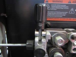
Spool Tensioner
This is the wire spool tensioner also known as the spool brake. If it is incorrectly tensioned the wire spool tends to over spool and ends up tangling the wire or creates excessive drag causing an erratic/restricted feed.
To correctly set the wire tension there is a nut with a spring that can be adjusted, the spool should stop fairly quickly when the trigger is released. Check to see that the spool is easy to turn, ensure that it is not fouling on the wire feed cover and that there are no obvious drag marks inside the wire feed unit.
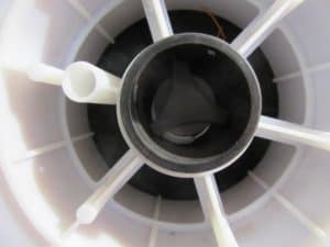
Spool tensioner in the centre of a wire spool
Without holding on to the spool, hold the trigger to release a small amount of wire. When stopped, ensure there is little or no sag in the wire between the spool and the drive roll mechanism. The wire should stop but still be able to be moved freely by hand without over spooling and having an excessive loop or wire between the spool and the rollers.
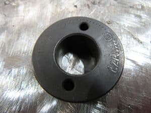
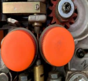
Drive Rolls
The drive rolls are extremely important, they come in a number of different types. ‘V-shaped’ rollers for solid wires, ‘U-shaped’ for soft wires, and knurled for tubular wires. The selection of the type and correct size is critical so as not to distort the wire; ensuring that when the wire passes through the contact tip it feeds constantly and maintains good contact.
Often the wire size is stamped on the drive roll and the size required is facing you when fitting the drive roll to the spindle, ensure the retaining nut or bolt is firmly in place but not over tightened.
 |
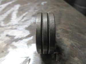 |
| Drive roll system | Knurled roll |
 |
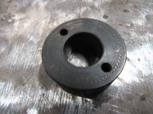 |
| Groove roll ‘V’ shape | Groove roll ‘V’ shape markings |
 |
 |
| Groove roll ‘U’ shape | Groove roll ‘U’ shape markings |
One common mistake that welders make when the wire is not feeding stably is tightening the tension on the spindle or drive rolls. By tightening the drive rolls you flatten the wire and when you flatten the wire it will not feed through the contact tip as intended. When soft wires such as aluminium or flux core tubular wire are flattened, instead of being 1.2mm round diameter, will be pressed into an oblong shape approximately 1mm by 1.4mm which will constantly jam in the tip. Drive roll tension should be as accurate as possible and can only be achieved by ensuring that all equipment is set up correctly.
Wire guide insert and rolls
Liner Types
Between the drive rolls and the entrance of the liner, there is usually an insert in the transfer block, this insert is there to guide the wire into the liner and to ensure it straightens the wire out. This insert should be placed approximately 3mm to 5mm from the leading edge of the drive rolls.
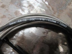
Liners come in a variety of different sizes and types. Correct selection of the liner is critical to ensure proper feeding of the wire, keep in mind the wire can be fed at 18 metres/minute so ensuring it is not obstructed is very important for consistent feed and therefore a consistent weld.
The type of liner is dependent on the type of material the liner is used for. Carbon steel, stainless steel, flux core, metal core use steel liners. Teflon is used for softer wire such as aluminium. If you use the aluminium wire and put it through a steel liner the aluminium wire will tend to strip inside the liner or create blockages and obstructions.
 |
 |
| Steel liner markings | Nylon liner markings |
Liner size
Liner size is another element to consider as it is not a one-size-fits-all approach. Suppliers usually have the liner size marked on the packet and on the liner itself. Sizes range from 0.9 to 1.2mm, 1.2 to 1.6mm, and 1.6 to 2.4mm. Using a liner that is too large will cause the wire to bunch up inside and create feeding issues. Conversely, a liner that is too small will jam up the wire inside the liner and the wire will not feed properly. It is recommended to use a liner that’s one size up from what is specified. For example, using a 0.9mm wire would require a 1.2 to 1.6mm liner to ensure the wire is supported and can feed without jamming.
 |
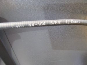 |
| Liner size markings 1.3mm – 1.6mm | Liner size markings 2mm |
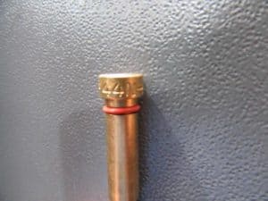
Contact tip
The contact tip is extremely important. It is where the power or energy is transferred from the power source to the wire to enable the wire to feed properly. High-quality contact tip is very important. First, make sure it is the right size. 0.9mm for 0.9mm wire or the contact between tip and wire is too inconsistent. The correct size is also very important with wires such as aluminium and tubular wires which are typically used at high-speed. You may need to use a heavy duty contact tip. These can be differentiated by physical size but they are also marked with a letter identifier so you will see 1.2H and 1.2A, H being heavy duty, A being Aluminium.
 |
| 1.2mm H contact tip |
Torch Length
Other elements not mentioned above include torch lengths. The torch length should be kept to a minimum, this ensures that the wire feed unit doesn’t drive the wire too far a distance from the drive roll to contact tip. For aluminium an ideal torch length without a push/pull gun or secondary feed unit is 3m to 3.6m, this is because the wire lacks rigidity, is soft, and if it tries to push the wire any further than that, from our experience you tend to have feed problems.
4m torches are the best length for bare wire and flux core wires for the same reason. This will ensure that the drive rolls don’t have to force the wire any more than 4m, which prevents feeding issues.
To understand this concept or theory use a piece a solid metal wire 0.9mm or 1.2mm flux cored wire. With one end in a vice, try and push that wire towards the vice. You will see what happens. This will help you to understand why torch length is critical when feeding a filler wire.
Liner Fitting
The fitting of the liner (cutting to the correct length) is often done incorrectly. The liner should fit comfortably into the diffuser without being forced but certainly should not fall short of the diffuser. The diffuser typically has a small grub screw, this needs to be firm but not over tightened or it will compress the liner and restrict wire feed.
 |
| Gas diffuser with grub screw |
Problem-free wire feeding
The quality of the fittings, torch, and contact tip are extremely important. When inexpensive contact tips are used, it is counterproductive as they don’t have the correct tolerances and tend to be softer. This results in worn contact tips being changed more frequently but more importantly, reduces off/on time because you’re constantly having to go to find new contact tips.
Another simple way to produce problem free feeding is to ensure the torch lead is relatively straight. Understandably, the tighter the radius and the more kinks and obstructions put on the torch, the harder it is for the wire to feed from the drive rolls through to the contact tip, this is one of the simple ways to ensure you do not encounter wire feeding issues and the wires burning back onto the tip.
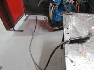 |
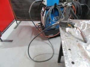 |
| Straight torch lead | Curled up torch lead |
Troubleshooting feeding issues
If the wire is not feeding correctly there are a variety of different elements within the wire feed system that can be isolated to determine which element is causing the problem. Start by releasing a small amount of wire out of the torch, unscrew the contact tip to ensure it is the correct size and ensure that the contact tip can move smoothly up and down the wire.
Once you have verified the contact tip is moving freely and is the correct size, verify that the liner is not the problem. Remove the tension from the drive rolls and slightly wind forward some wire so it is not dragging on the tensioner, hold the wire at the torch end and then pull the wire through the liner, it should move freely. If it doesn’t it means you have a blockage or kink in the line.
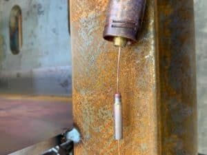 |
 |
| Contact tip moving freely along wire | Drive roll tensioner |
Drive roll tension should be set so when the wire creates a little resistance, the drive roll slips rather than bunch the wire up between the drive rolls and the insert or entry point into the torch. This can be checked by backing the tension off the drive roll tensioner then holding the torch close to a piece of timber and pulling the trigger so when the wire hits the timber the drive rolls still drive, yet the wire slips rather than continuing to force the wire past the obstruction.
Spool spring tension is the other element that people are unaware of, it should be tensioned enough to prevent the spool from over-rolling or over-winding. This results in the wire being released from the spool. If tensioned too tight, it can drag on the spool, put excessive load on the wire and the drive rolls, and prevent adequate feeding.
If you are interested in further developing your welding knowledge, visit our training page for upcoming courses. Stay tuned for part two of the GMAW blog series where we will break down the gas shielding system and discuss the function, parts involved and how to troubleshoot gas shielding issues.